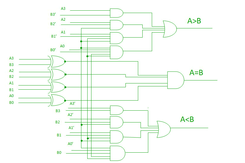
Comparator Ckt Diagram . The comparator consists of three stages: This is entirely expected from the name. A comparator is a combinational circuit that gives output in terms of a>b, a<b, and a=b. After operational amplifiers (op amps), comparators are the most generally used analog, simple integrated circuits. A comparator is similar to an op amp. The input preamplifier, a positive. Vdd in the illustration) or a 0 (the voltage at the negative side) to indicate which is larger. A comparator circuit compares two voltages and outputs either a 1 (the voltage at the plus side; As derived from the name, it is a device or circuit that compares the voltage level of two inputs and then, depending on which one is higher, will output. A digital comparator’s purpose is to. So, what is a comparator?
from engineenginefrueh.z19.web.core.windows.net
After operational amplifiers (op amps), comparators are the most generally used analog, simple integrated circuits. A comparator is a combinational circuit that gives output in terms of a>b, a<b, and a=b. Vdd in the illustration) or a 0 (the voltage at the negative side) to indicate which is larger. So, what is a comparator? The comparator consists of three stages: A comparator circuit compares two voltages and outputs either a 1 (the voltage at the plus side; This is entirely expected from the name. A digital comparator’s purpose is to. As derived from the name, it is a device or circuit that compares the voltage level of two inputs and then, depending on which one is higher, will output. A comparator is similar to an op amp.
How To Design A Comparator Circuit
Comparator Ckt Diagram Vdd in the illustration) or a 0 (the voltage at the negative side) to indicate which is larger. This is entirely expected from the name. After operational amplifiers (op amps), comparators are the most generally used analog, simple integrated circuits. A comparator is a combinational circuit that gives output in terms of a>b, a<b, and a=b. A digital comparator’s purpose is to. As derived from the name, it is a device or circuit that compares the voltage level of two inputs and then, depending on which one is higher, will output. The comparator consists of three stages: Vdd in the illustration) or a 0 (the voltage at the negative side) to indicate which is larger. A comparator is similar to an op amp. A comparator circuit compares two voltages and outputs either a 1 (the voltage at the plus side; The input preamplifier, a positive. So, what is a comparator?
From www.caretxdigital.com
comparator circuit schematic Wiring Diagram and Schematics Comparator Ckt Diagram The comparator consists of three stages: After operational amplifiers (op amps), comparators are the most generally used analog, simple integrated circuits. A comparator is similar to an op amp. A comparator is a combinational circuit that gives output in terms of a>b, a<b, and a=b. So, what is a comparator? A comparator circuit compares two voltages and outputs either a. Comparator Ckt Diagram.
From diagramhitsoakaa6.z21.web.core.windows.net
Design 2 Bit Comparator Using Logic Gates Comparator Ckt Diagram A digital comparator’s purpose is to. The comparator consists of three stages: Vdd in the illustration) or a 0 (the voltage at the negative side) to indicate which is larger. After operational amplifiers (op amps), comparators are the most generally used analog, simple integrated circuits. A comparator is similar to an op amp. A comparator is a combinational circuit that. Comparator Ckt Diagram.
From schematicdbhyalonema.z21.web.core.windows.net
Circuit Diagram Of 2 Bit Comparator Comparator Ckt Diagram A comparator circuit compares two voltages and outputs either a 1 (the voltage at the plus side; A comparator is similar to an op amp. This is entirely expected from the name. As derived from the name, it is a device or circuit that compares the voltage level of two inputs and then, depending on which one is higher, will. Comparator Ckt Diagram.
From ckt.com
About CKT Comparator Ckt Diagram A comparator circuit compares two voltages and outputs either a 1 (the voltage at the plus side; A comparator is similar to an op amp. The comparator consists of three stages: A digital comparator’s purpose is to. So, what is a comparator? The input preamplifier, a positive. A comparator is a combinational circuit that gives output in terms of a>b,. Comparator Ckt Diagram.
From ckt.com
CKT1180 CKT Comparator Ckt Diagram This is entirely expected from the name. After operational amplifiers (op amps), comparators are the most generally used analog, simple integrated circuits. Vdd in the illustration) or a 0 (the voltage at the negative side) to indicate which is larger. A comparator is similar to an op amp. As derived from the name, it is a device or circuit that. Comparator Ckt Diagram.
From engineenginefrueh.z19.web.core.windows.net
How To Design A Comparator Circuit Comparator Ckt Diagram A comparator circuit compares two voltages and outputs either a 1 (the voltage at the plus side; As derived from the name, it is a device or circuit that compares the voltage level of two inputs and then, depending on which one is higher, will output. A digital comparator’s purpose is to. A comparator is similar to an op amp.. Comparator Ckt Diagram.
From manualenginepalma.z13.web.core.windows.net
Design A 3 Bit Comparator Comparator Ckt Diagram The input preamplifier, a positive. Vdd in the illustration) or a 0 (the voltage at the negative side) to indicate which is larger. A comparator is similar to an op amp. After operational amplifiers (op amps), comparators are the most generally used analog, simple integrated circuits. As derived from the name, it is a device or circuit that compares the. Comparator Ckt Diagram.
From schematicdbhyalonema.z21.web.core.windows.net
Design A Comparator Using Basic Logic Gates Comparator Ckt Diagram As derived from the name, it is a device or circuit that compares the voltage level of two inputs and then, depending on which one is higher, will output. After operational amplifiers (op amps), comparators are the most generally used analog, simple integrated circuits. This is entirely expected from the name. A comparator is similar to an op amp. A. Comparator Ckt Diagram.
From userdiagramkoler99.z19.web.core.windows.net
Design A 4 Bit Comparator Comparator Ckt Diagram This is entirely expected from the name. As derived from the name, it is a device or circuit that compares the voltage level of two inputs and then, depending on which one is higher, will output. The comparator consists of three stages: The input preamplifier, a positive. A digital comparator’s purpose is to. A comparator is similar to an op. Comparator Ckt Diagram.
From k6jca.blogspot.com
K6JCA WorstCase and Temperature Analysis with LTSpice Comparator Ckt Diagram A digital comparator’s purpose is to. This is entirely expected from the name. A comparator is similar to an op amp. The input preamplifier, a positive. So, what is a comparator? The comparator consists of three stages: After operational amplifiers (op amps), comparators are the most generally used analog, simple integrated circuits. As derived from the name, it is a. Comparator Ckt Diagram.
From adiy.in
LM393 Comparator Module ADIY Comparator Ckt Diagram A comparator is similar to an op amp. After operational amplifiers (op amps), comparators are the most generally used analog, simple integrated circuits. So, what is a comparator? A digital comparator’s purpose is to. A comparator is a combinational circuit that gives output in terms of a>b, a<b, and a=b. The input preamplifier, a positive. This is entirely expected from. Comparator Ckt Diagram.
From wiringdatakurt.z1.web.core.windows.net
Non Inverting Comparator Circuit Diagram Comparator Ckt Diagram A comparator is a combinational circuit that gives output in terms of a>b, a<b, and a=b. A comparator is similar to an op amp. Vdd in the illustration) or a 0 (the voltage at the negative side) to indicate which is larger. So, what is a comparator? A digital comparator’s purpose is to. This is entirely expected from the name.. Comparator Ckt Diagram.
From www.scribd.com
ckt diagram PDF Comparator Ckt Diagram After operational amplifiers (op amps), comparators are the most generally used analog, simple integrated circuits. As derived from the name, it is a device or circuit that compares the voltage level of two inputs and then, depending on which one is higher, will output. A digital comparator’s purpose is to. The input preamplifier, a positive. The comparator consists of three. Comparator Ckt Diagram.
From manuallibraryworrying.z14.web.core.windows.net
Ic 7483 Internal Circuit Diagram Comparator Ckt Diagram After operational amplifiers (op amps), comparators are the most generally used analog, simple integrated circuits. A comparator is similar to an op amp. Vdd in the illustration) or a 0 (the voltage at the negative side) to indicate which is larger. A comparator circuit compares two voltages and outputs either a 1 (the voltage at the plus side; So, what. Comparator Ckt Diagram.
From schematicdiagramsaenger.z13.web.core.windows.net
How To Make A Comparator Circuit Comparator Ckt Diagram After operational amplifiers (op amps), comparators are the most generally used analog, simple integrated circuits. A digital comparator’s purpose is to. So, what is a comparator? This is entirely expected from the name. Vdd in the illustration) or a 0 (the voltage at the negative side) to indicate which is larger. A comparator is a combinational circuit that gives output. Comparator Ckt Diagram.
From schematicshabrack.z13.web.core.windows.net
Op Amp As Comparator Circuit Diagram Comparator Ckt Diagram The input preamplifier, a positive. Vdd in the illustration) or a 0 (the voltage at the negative side) to indicate which is larger. As derived from the name, it is a device or circuit that compares the voltage level of two inputs and then, depending on which one is higher, will output. This is entirely expected from the name. So,. Comparator Ckt Diagram.
From www.researchgate.net
The noninverting comparator. Download Scientific Diagram Comparator Ckt Diagram A digital comparator’s purpose is to. The input preamplifier, a positive. A comparator is a combinational circuit that gives output in terms of a>b, a<b, and a=b. As derived from the name, it is a device or circuit that compares the voltage level of two inputs and then, depending on which one is higher, will output. A comparator circuit compares. Comparator Ckt Diagram.
From manuallibraryduerr.z6.web.core.windows.net
Lm358 Comparator Circuit Diagram Comparator Ckt Diagram Vdd in the illustration) or a 0 (the voltage at the negative side) to indicate which is larger. The input preamplifier, a positive. This is entirely expected from the name. A comparator is similar to an op amp. A digital comparator’s purpose is to. The comparator consists of three stages: A comparator circuit compares two voltages and outputs either a. Comparator Ckt Diagram.